


Composition Module
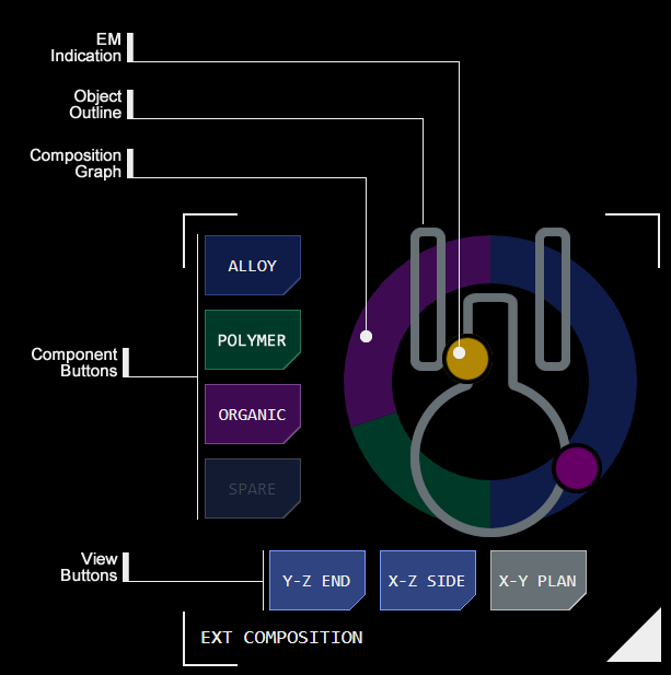 The composition module provides a visualisation of the composition of a scanned object.
Up to four components and their relative proportions are displayable, each designated using the Standard Designation Display Protocol (SDDP).
The module can be switched between two display modes by the user: exterior analysis and interior analysis.
Component Distribution
The module visualises the distribution of components as a donut graph.
Each component is represented by an SDDP colour and has a button of a matching colour.
Tapping the button displays an overlay with greater detail about the component.
Exterior Analysis
The module displays the percentage each major component contributes to the object's surface makeup, visualised as a pie graph.
The major components are also represented as buttons to the left of the module, with each button's colour corresponding to the matchng colour in the graph. Each button is labelled with the component's class.
The bottom-left module label updates to indicate exterior mode is being viewed.
Analysis Detail Display
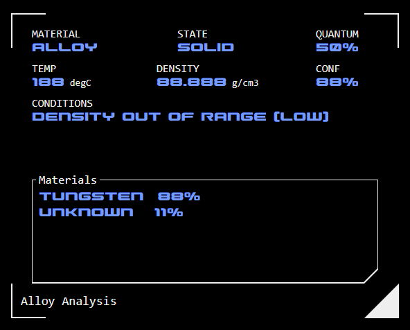 Tapping a component button launches an overlay which displays greater analysis detail.
Material: This is the component's assessed material class
State: This is the material's state (eg solid, liquid, gas, plasma) at the current temperature
Quantum: This is the percentage of the objects overall composition represented by this component
Temperature: The current (average) temperature of this component
Density: The estimated density of the component's material
Conf(idence): The confidence of the AI assessment generating the component analysis
Condiitons: Any unusual conditions arising from the component analysis
Materials: Where available a list of the component's constituent elements.
Interior Analysis
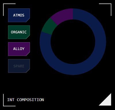 The module displays the percentage each major component contributes to the object's interior makeup, visualised as a pie graph.
The major components are also represented as buttons to the left of the module, with each button's colour corresponding to the matchng colour in the graph. Each button is labelled with the component's class.
The bottom-left module label updates to indicate interior mode is being viewed.
Component Classes
Components are represented as a material class, based on AI assessments of the available data.
EM Distribution Analysis
Where the system has sufficient data on the scanned object's configuration/shape it can display localised prominent EM emissions relative to their location on the object's exterior.
This display is only supported in exterior mode.
A simplified outline of the object is displayed as an overlay over the composition analysis graph. Indicator dots show where EM is detected relative to that outline, with the colour of the dots indicating the EM band of the emission using the standard EM Designation Protocol (EMDP).
Different object orientations can be selected using the view buttons at the bottom of the module.
Object Orientation
The EM distribution analysis provides a 2D representation of a 3D object by selecting one of the object’s 3D cartesian planes to present as an orthographic projection, similar to the way an object is represented in a technical drawing.
The scan analysis will make an estimate of an object’s orientation (ie where its bow or forward face is located) based on configuration (for vessels) and/or direction of movement. For naturally occurring objects the orientation may be set arbitrarily.
The three object planes used are:
Y-Z Plane (end elevation): This visualises the object as if looking directly towards its bow or front face.
X-Z Plane (side elevation): This visualises the object as if looking at it directly from abeam (towards its side face). In this elevation the object’s bow (or forward face) would be to the left of the display.
X-Y Plane (plan elevation): This visualises the object as if looking directly at it ventrally (from above). In this elevation the vessel’s bow (or forward face) would be to the bottom of the display.
Concept Site
Immersive sci-fi and how to join the adventure
Crew Site
Information and tools for ISDC crew members


