


Navigation Radial Module
 The navigation radial is a multi-mode control and data visualisation designed to support navigation processes.
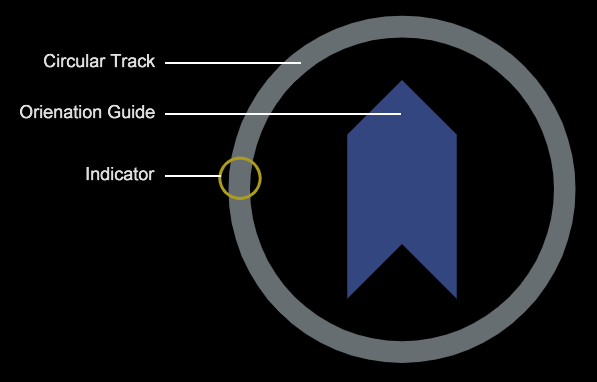
The design incorporates a large circular track over which an indicator gives a visual indication of the monitored bearing/heading relative to a central graphic showing the vessel’s orientation. In control mode (see below) the track becomes a selection dial.
Module Modes
The navigational radial has three configurable modes.
Mode 0: Location Indicator
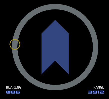 This mode provides a visualisation of the bearing and range of a target location. The track/indicator combination displays the bearing. The indicator colour is gold in this mode.
Numerical values are displayed at the bottom of the module.
Display Sources
Display data can be switched between a primary and alternative source.
The circular track will display in a different colour when displaying the alternative source.
Mode 1: Control
This mode uses the circular track as a selection dial, with the indicator showing the current selection. The indicator colour is blue in this mode.
The numerical value displayed at the bottom left.
This mode includes two orientations.
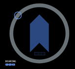 Orientation 0: Bearing Mode
This mode is designed for bearing input.
The orientation guide is positioned vertically. Zero is positioned at the top of the track and 180 at the bottom. Port values are positive, starboard values are negative.
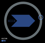 Orientation 1: Vector Mode
This mode is designed for vector input.
The orientation guide is positioned horizontally. Zero is positioned at the right of the track and 180 at the left. Dorsal values are positive, ventral values are negative.
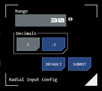 Selection Range
In this mode the base of the orientation guide includes an indicator which shows the maximum selection range in each direction (by default this is 180 degrees).
Tapping the indicator opens a configuration interface which allows the user to adjust the selection range for that module instance
The numerical input sets the maximum range in degrees (which cannot exceed 180).
The decimal buttons set the desired level of granularity - whether the selection should include a decimal place (the .1 button) or not (the 1 button).
Mode 2: Position Indicator
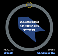 This mode (also referred to as "compass mode") provides the vessel’s current position. The vessel's headng relative to galactic normal (the top of the circular track) is shown by the central orientation graphic.
Numerical values for heading and speed are provided at the bottom of the module.
The vessel’s position on the impulse navigation grid is overlayed as X,Y & Z coordinates in the centre of the module.
When in this mode the module sources data from the Navigation Objects database.
Broadcast Site
Latest episodes and background information
Crew Site
Information and tools for ISDC crew members


