


PDN sim

Power is distributed between power sources and vessel systems by conduits. Each conduit is designed for distributing a particular type of power and will have a maximum rating for the amount of power (current) it can handle.
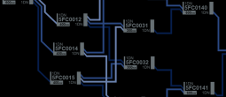
Conduits connect power distribution nodes. Each node is connected to both upstream conduits (which deliver power from other nodes closer to power generation systems) and downstream conduits (which distribute power to other nodes closer to the vessel systems that consume power. A node will typically convert power to a new standard before distributing to downstream nodes, with distribution parameters configurable for each node. Each node typically has a number of both upstream and downstream conduits to ensure redundant power routing options and for efficent power distribution.
Vessel systems will typically be able to access multiple nodes to ensure redundancy of power supply.
Nodes
Nodes manage the conversion and distribution of power from power generation systems to the vessel systems that consume power. A node receives power via conduits connected to its upstream interface and will typically convert the upstream (supply) power standard to a different downstream power standard (for example high voltage or frequency to low voltage/frequency). The node will then distribute power to conduits connecetd to its downstream interface. Each node is constructed for a specific standard conversion and cannot be configured to receive or distribute alternative power standards.
Each node has a control interface which allows the allocation of power to downstream conduits, allowing management of power routing.
Nodes are connected to conduits via conduit taps. A conduit tap provides access to all other nodes on that conduit, depending on whether the conduit is connected on that node's upstream or downstream interface. For example, a connection on a node's upstream interface (which receives power) will give access to power from all nodes with a downstream connection (which supplies power) to that conduit.
Most nodes are distribution nodes that have both upstream and downstream interfaces. The PDN also considers power supply systems and major vessel systems as nodes, known as terminating (single-interface) nodes. Power supply systems are source nodes (they supply but do not receive power) and major vessel systems are consumption nodes (they receive but do not supply power).
Nodes are defined by the following parameters:
NodeID: A unique identifier for the node (see this article for designation standards)
Type: Description of the type of node:
Distribution: The most common type of node, has both upstream and downstream conduits. Downstream supply (see below) can be configured between downstream nodes.
Source: The node is a power source and so does not have upstream conduits. Downstream supply (see below) is configured in the same way as distribution nodes.
Consumption: The node is a vessel system that consumes supplied power. Upstream supply for these nodes is configurable, so that the system operator can choose how much power the system actually draws from what is available.
Conduits: The conduits the node connects to:
- Conduit UID: The conduit's unique ID
- Supply Interface: Whether the conduit is connected to the upstream or downstream interface of the node
Upstream Standard: The power standard that can be recieved by the node:
- 1DN: mid-voltage (1000V) DC
- 2DNH: 440v high frequency (400Hz)
- 2DNL: 240V 50Hz
Downstream Standard: The power standard that can be delivered by the node:
- 1DN: mid-voltage (1000V) DC
- 2DNH: 440v high frequency (400Hz)
- 2DNL: 240V 50Hz
Maximum Capacity: The maximum upstream current this node can carry
Available Capacity: The maximum upstream current this node can currently carry
Upstream Supply: The amount of upstream current currently available (as an aggregate of the current supplied from all upstream conduits).
Downstream Allocation: The amount of current allocated to downstream conduits. Each downstream conduit will have it's own attributes:
Conduit UID
Allocated: The current allocated to the downstream node, as a percentage of upstream supply
Committed: The amount of downstream current allocated (as an aggregate across all downstream conduits)
Status:
- Nominal: Operating to specification and in use (displays as Engaged for auxiliary supply nodes)
- Marginal: The node has been impaired and available capacity is less than maximum
- Offline: The node is unavailable and cannot receive or supply power (offline status is selected either automatically when system sfaeguards are breached or manually by an operator)
- Standby: (for auxiliary supply nodes only) Operating to specification and available for use (but not currently supplying power)
Priority: The relative priority of this node from 1 (critical) to 12 (lowest priority). This is used to calculate which nodes should continue receive power if available power drops below committed power (due to upstream damage, for example).
Conduits
A conduit distributes power between nodes. Nodes can connect to conduits via a conduit tap to either supply power (via the node's downstream interface) or receive power (via the node's downstream interface). The vessel's PDN is designed to provide as much flexibility and redundancy for power distribution as possible, minimising the need to make new connections unless damage or extraordinary operational requirements make this necessary. Conduits are rated for a particular power standard, although in some cases can distribute other standrds at reduced efficiency.
Conduits are defined in the simulator by its reference number. Additional parameters specific to the conduit are also stored:
Conduit ID: A unique identifier (see this article for designation standards)
Type: Whether the conduit is designed for high voltage or high frequency distribution.
- 1DN: mid-voltage (1000V) DC
- 2DNH: 440v high frequency (400Hz)
- 2DNL: 240V 50Hz
Maximum Capacity: The maximum current that a conduit can carry under nominal operating conditions. Where the current exceeds maximum rating, a conduit load event is calculated (the probability of an event increasing the more maximum load is exceeded).
Available Capacity: The maximum current a conduit can carry under current operating conditions (ie after any damage)
Load: The current presently being carried by the conduit (and aggregate of power committed by all nodes with a downstream interface to the conduit - see below)
Status: The status of the conduit:
- Nominal: Operating to specification and in use
- Marginal: The conduit has been impaired and available capacity is less than maximum
- Note: Conduits cannot be taken offline, although they can be routed around.
Supply Management
Management of power supply across the PDN is a two-way process. Allocation of power is configured from generation systems down through the PDN to ensure effcient allocation to all vessel systems. Consumption of power is indicated by the committed power usage of vessel sytems and works its way from vessel (consumtption) systems up through the PDN to ensure that changes to power allocation do not have unintended consequences such as critical system outages.
Each node in the PDN has a standard configuration designed to manage power distribution during standard vessel operations. This standard configuration can be overridden on a node-by-node basis if needed so that power can be re-routed to meet exceptional demand or avoid damaged parts of the PDN.
Available Power
Available power is an allocation from an upstream node that may be drawn on by a downstream node. This starts at a supply node and works it's way down the PDN. Each node aggregates the power available via its upstream conduits and allows this (once converted) to be allocated to each of its downstream conduits. Standard allocations are pre-configured in the system for normal operation, but can be overridden manually or in some cases automatically depending on the priority of the downstream node.
Allocation of available power can be adjusted at any time although committed power requirements from downstream nodes are displayed to guide allocation and prevent unintended blackouts.
Committed Power
Committed power involves a downstream node reporting it's current allocations to its upstream conduits. This starts at a consumption node and works its way up the PDN to avoid allocation changes made upstream having unintended consequences.
System users will see all of the upstream nodes accessible by their system on their consoles and be able to select the appropriate source and define the amount of power being committed.
A committment of power by a system (consumption node) is aggregated with those of all other systems connected to the upstream node. This aggregated commit is then aggregated by the next upstream node, and so on up the PDN until a supply node is reached. Subject to operational safeguards, commitments at any node can be overrridden, but great care must be taken because any reallocation of previously committed power may have unforseen circumstances downstream.
Supply Routing
A node aggregates the power available from all all conduits connected to its upstream interface. As most conduits will have multiple upstream taps, each node will see the same power availability. As one node allocates power, this reduces the power available to the other connected nodes. Power allocation and routing is therefore a balancing act between the competing demands of downstream nodes and systems.
Power Reserve
The design of the PDN allows for adequate power allocation to all systems under standard operating conditions. Typically, not all power from an upstream node will be allocated, leaving a contingnecy or reserve that can be allocated by any connected node as needed without major, multi-node routing adjustments.
Categories:
Concept Site
Immersive sci-fi and how to join the adventure
Crew Site
Information and tools for ISDC crew members


