


Reactor Generator Simulation
The reactor generator is a sub-system of the secondary coolant loop, but is treated as a separate system for the sake of clarity.
The generator uses the steam created by the thermal exchanger to drive a turbine. The turbine drives an alternator which produces electrical power. This power is converted by the power distribution network (PDN) to the various standards required by vessel systems.
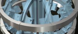
Steam Concentrator
 The steam from the thermal exchanger is concentrated before being released into the turbine as a high-velocity stream through a series of jets. This increases the working pressure of the steam. The concentrator has a relatively narrow response profile.
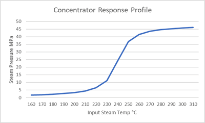
Function
The steam concentrator response profile is described as a gaussian cumulative distribution, where:
X is the input temperature of the steam from the thermal exchanger
Width is 18
Centre is 240
Modifier is 48
The output of the function is the concentrated steam pressure, with a nominal value of 24MPa.
Steam Bleed
Where steam input temperature is above nominal and may produce concentrated steam pressures too high for the alternator, steam can be bled off from the concentrator, reducing the output pressure.
This steam is sent directly to the RHSA. The steam bleed has the same impact on steam temperature as the turbine, and so steam reaching the RHSA this way is the same temperature as that coming out of the turbine. As the secondary loop is a closed loop, the volume of coolant entering the RHSA does not vary with the source (bleed or turbine).
Steam Moisture
The amount of steam moisture (steam in a semi-condensed state) increases as the pressure within the turbine increases. This is described using the same gaussian cumulative distribution as the steam concentrator, but with a different modifier:
Modifier is 28
The output is the percentage of steam moisture to steam volume.
This variable will be used to track the status of the turbine blades, which can be expected to corrode with use, a process that is accelerated by higher steam moisture levels.
This is currently stubbed.
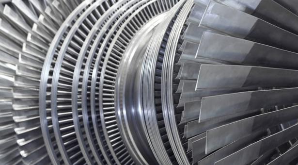
Turbine
 The turbine is made up of a series of turbines with different profile blades.
Pure blades are moved by the energy of the stream striking them. Nozzles lower the pressure and increase the velocity of the steam.
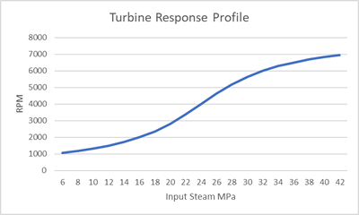
Function
The response profile of the turbine to incoming steam pressure from the steam concentrator is also described by a gaussian cumulative distribution, where:
X is incoming steam pressure from the concentrator
Width is 16
Centre is 24
Modifier is 8000
Output is revolutions per minute with a nominal value of 4000RPM.
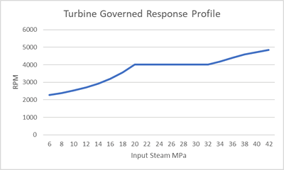
Governor
For the alternator to maintain correct power frequency, the turbine must spin at a constant rate. The governor is responsible for correcting variances in the turbines operating parameters that would otherwise cause a variation from nominal RPMs.
 The governor uses both mechanical limiters and computer-controlled pitch adjustments to the turbine’s blades for managing turbine RPMs. This dual-technique approach allows the turbine to be slowed or sped up as required.
The governor is effective within a certain range of RPMs:
Over-speed: 2100 RPM (ie up to 2100RPMs can be removed from turbine speed)
Under-speed:1200 RPM (ie up to 1200RPM can be added to turbine speed)
Engineering Event
[STUB] Pre-governed turbine speeds above a certain RMP value will cause turbine damage.
Alternator
The alternator is a relatively simple component. It outputs a constant 400MW if the turbine is turning.
The output frequency of power generated will vary with input RPMs. The frequency is output in KHz and calculated by dividing input RPMs by the conversion factor (10).
Variations in RPMs doesn’t impact the alternator itself, but variations in output frequency may disrupt downstream systems.
Categories:
Concept Site
Immersive sci-fi and how to join the adventure
Crew Site
Information and tools for ISDC crew members


