


Active Sensor Simulation
The active sensor system uses scans (it projects EM against a target and analyses any returned EM) to provide data on the shape/configuration and composition of objects in space.
There are two types of scan. A low-power scan (so called because it uses lower radio-band EM for scans) provides data about the exterior of an object.
A high power scan (which uses high frequency ionising-band EM for scans) provides data about the interior of an object.
The results of scans are visualised on the Scan Analysis panel. This provides:
- a 3D visualisation of the scanned object (which can be rotated around 2 axes by the user) for both exterior and interior scans
- A breakdown of the main materials composing the object's exterior or interior (depending on the scan mode)
- Current EM output of the scanned object at source
- An overview of where EM emisisons are concentrated on a simplified outline view of the object
The level of detail provided by the panel depends on the intensity and length of scans. The longer and/or more intense (power output) a scan is, the higher the scan's fidelity and the more detail is shown.
Scan Data Source
The data for these visualisations are stored for each vessel in the simulator's navigation objects database, as part of the vessel's designation.
3D Models
The 3D models which will be displayed once scans have been completed are referenced in the designation.
Each object has at a minimum an exterior 3D model. An interior 3D model is also required unless interiror scans are prevented (by energy shielding or other interference, for example).
Fidelity Levels
Each 3D model will require four variants, each representing a different level of fidelity:
Low: here
Medium: here
High: here
Top: here
Display is triggered if scan fidelity reaches the minimum level for that variant.
Materials
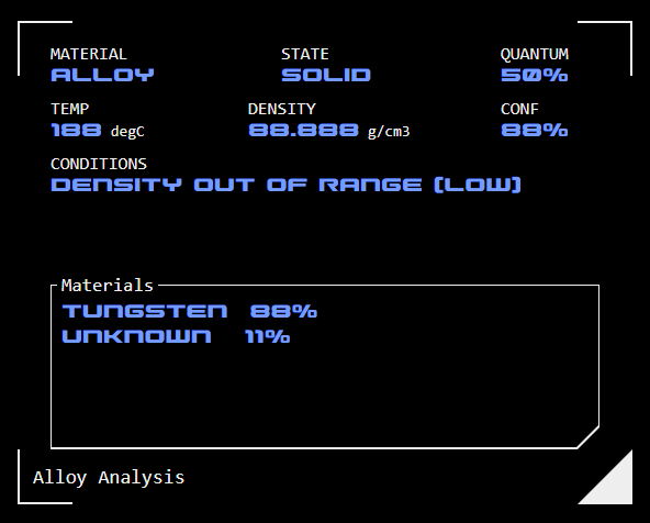 Data for each material composing the object needs to be defined for both interior and exterior scans. A maximum of four materials are displayed in the main view of the composition module.
Where there are more than four materials, in the main view the last button becomes the "OTHER" button - tapping this allows the other materials to be accessed via an overlay. The corresponding segment on the graph is the total of all "other" materials are added together.
Materials include the following data (all are required fields unless indicated by an asterisk):
Class: The composition class
Value: Numeric value representing the percentage of this material in the object's overall makup (repeated as quantum in the detail display - it doesn't need to be entered twice).
Material: This is usually a repeat of the Class, but can be the sub-class if applicable.
State: The material's state (solid, liquid, gas, plasma) at its current temperature
Temp: The material's current temperature in degrees celcius.
Density: The material's density in gm/cm3
Conf: The confidence of the AI analysis (as a percentage).
Conditions*: Up to three conditions,typically calling out an anomaly (eg where the density is lower than expected for the material type).
Materials: The elements (or molecules) making up the object along with the percentage of overall makeup. "Unknown" is acceptable where not every element can be identified. Where no elements can be identified "unknown" is required as a minum entry.
EM Overlay
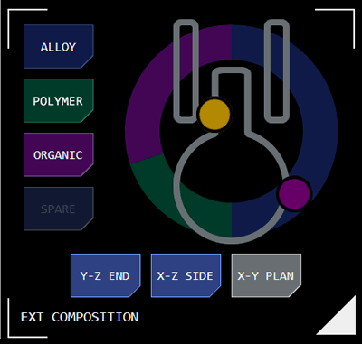 The compostion module can display detected concentrations of EM output against a particular location on the scanned object, for example at the location of engine or weapons output.
This is displayed as an EM indicator (a coloured dot) at the approximate location on the object (the object is represented as a simplified outline). The colour of the dot represents the EM band of the emission. The object can be viewed from three different perspectives (end. side and top/plan). The EM indicator is only displayed where there is EM output from the object in that EM band.
The EM band of the EM indicator dot needs to be defined. The position of the EM indicator needs to be defined for each of the three views.
EM indicators must be defined for each scan state.
EM Overlay State
Up to five EM indicator states can be defined and selected for display independent of scan state.
This is useful where a producer wishes to control when an EM indicator becomes visible independently of overall EM output in that band (ie where there are multiple systems emitting EM in that band).
Scan State
It is possible to pre-define up two five different variations of an object, which may represent the objects transformation during the course of a mission (for example if it reconfigures or takes major damage). Each variation is referred to as a scan state.
During a mission the scan state can be changed via the sim admin panel, by selecting the relevant ship and tapping the CONFIG tab.
Variations of all datapoints must be stored for each state that may be used during a mission.
Concept Site
Immersive sci-fi and how to join the adventure
Crew Site
Information and tools for ISDC crew members


