


Orientation Module
The orientation module is a backend API that calculates the range and bearing of other objects on the TOE grid based on their relative grid position.
The sim also uses the headings of the vessel to calculate facing profile planes.
Bearing
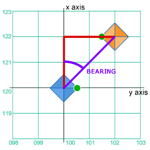 An object’s bearing is triangulated from it’s relative grid position, using the vessel’s own grid position as the origin. Subtracting the objects grid co-ordinates from the vessel’s gives the grid shift between vessel and object.
In the example diagram, the vessel (blue) has a grid position of X120, Y122. The TSMO (orange) has a grid position X122, Y102. The grid shift is X2, Y2. This gives a triangulated bearing of 45°, which is the raw bearing of the TSMO.
Raw Bearing Calculation
where R is the raw bearing, xs and ys are the grid shift values for the X and Y axes.
Direct Alignment
If a grid shift value is zero then an object is directly aligned along the other axis. The value of the other axis is used to determine the raw bearing.
Where the X-shift is zero, then a positive Y-shift value indicates the object is on the port beam.
Where the Y-shift is zero, then a negative X-shift value indicates the object is astern.
Conversion to Bearing Standard
Raw bearings are expressed in a range of zero to 360°, whereas to assist with navigation, bearings are expressed from the vessel’s bow, up to 180° to port or starboard. Starboard bearings are expressed mathematically as negative values. The raw bearing is adjusted to fit within the -180°/180° bearing standard.
Directionally Shifted Bearing
A raw bearing can be triangulated from the grid shift, but this assumes that the vessel has a zero-degree heading. As bearings are relative to the vessel’s bow, the raw bearing must be adjusted to reflect the vessel’s actual heading.
where B is the directionally shifted bearing, Rc is the standardised bearing and H is the vessel’s current heading.
Reverse Bearing Correction
The directionally shifted bearing calculation may give a result outside the +/-180° range and so must be corrected to conform to the bearing system.
where Bc is the standardised bearing.
Profile Plane
The profile plane facing the object is calculated from the directionally-shifted bearing by rounding the bearing to the nearest denominator of 90°. This simplified model that assumes only one profile plane at a time is facing an object.
| Bearing | Facing Plane |
|---|---|
| < -90° | 4 |
| < 0° | 2 |
| > 0° | 1 |
| > 90° | 3 |
Direct Lateral Alignment
If any grid-shift value is zero (see above) then the object is directly aligned with the vessel on one axes. This means that multiple profile planes are facing the object.
For lateral alignment (where X or Y-shift values are zero):
| Alignment | Facing Planes |
|---|---|
| Ahead | 1 & 2 |
| Astern | 3 & 4 |
| Port Beam | 1 & 3 |
| Starboard Beam | 2 & 4 |
Vector Correction
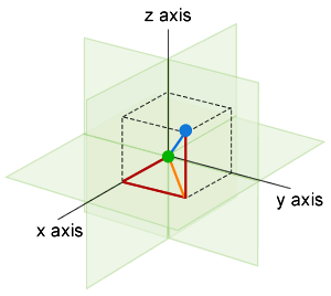
If there is a Z-shift then the object may be above or below the vessel. The facing profile plane is adjusted accordingly.
If the Z-shift has a positive value then the object is above the vessel and the facing profile plane is not adjusted (the vessel’s dorsal profile planes are facing the object).
If the Z-shift as a negative value then the object is below the vessel. The facing profile plane is adjusted by adding four. This indicates which of the vessel’s ventral profile planes are facing the object.
Direct Alignment
If the Z-shift is zero then the object is directly aligned vertically. Any profile planes facing laterally have four added to them. The new values are the additional planes that are facing the object.
| Lateral Facing | With Vertical Alignment |
|---|---|
| 1 | 1 & 5 |
| 2 | 2 & 6 |
| 3 | 3 & 7 |
| 4 | 4 & 8 |
| 1 & 2 | 1,2,5,6 |
| 2 & 4 | 2,4,6,8 |
Range
 Range to an object is calculated in two parts.
First, the distance to the object along the bearing is calculated from the X and Y shift. If either the X or Y-shift value is zero, then the range is the other shift value, without need for further calculation.
If there is a vector to the object (the Z-shift is <> zero), then a second calculation is needed to give the range.
Negative Shift Correction
A negative grid-shift value (where a TSMO is astern, to starboard or below the vessel) may result in a negative range. The result is inversed to cancel out the negative value.
Module Details
Script: ../view/nav/contacts/orientation.js
Functions
- getBearing(request)
Input Parameters
Input parameters are supplied as an object:
{
vessel: { The vessel is the query origin
gridX:
gridY:
gridZ:
heading:
},
tsmo: { The TSMO is the query target
gridX:
gridY:
gridZ:
heading:
}
}
Output Parameters
Output parameters are returned as an object:
{
bearing: This is the bearing of the TSMO relative to the vessel
facingPlane: This indiates which of the vessel's planes is facing the TSMO
vector: This is the vector of the TSMO relative to the vessel
range: This is the distnace between the vessel and the TSMO
gridX: This is the grid shift (difference in grid positions) on the X axis
gridY: This is the grid shift (difference in grid positions) on the X axis
gridZ: This is the grid shift (difference in grid positions) on the X axis
}
Categories:
Concept Site
Immersive sci-fi and how to join the adventure
Crew Site
Information and tools for ISDC crew members


