


Toroidal Generator Simulator
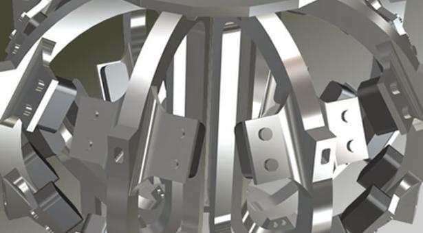
Toroidal Field Generators (TGEN) are powerful super-conducting magnets that create the main magnetic field for containing the high-temperature plasma that fuel the fusion systems within the reactor simulation. There are eight toroidal generators surrounding the reactor with the portion of the reaction chamber falling between a facing pair of toroidal generators creating a reactor segment.
The toroidal containment system manages the output of these generators against power input into them. A number of factors impact the efficiency of this power response profile, most notably power loading and operating temperature.
Overview
There are eight Toridal Field Generator systems (TGENs) used to create the main magnetic containment field for the fusion reactor. Power is supplied and managed individually for each generator.
The output from a toroidal field generator is a magnetic field, the magnitude (strength) of which is measured in teslas (T). The magnitude produced by the generator at a given power input level is described by the generator's response profile (defined below).
The response profile is impacted by the operating temperature of the generator (TGENx OpTemp). The operating temperature is determined by the Environmental Heat Load (EHL) radiating from the reactor wall as modified by the Tertiary Cooling System (TCS).
Each toroidal generator has an independent cooling unit - together these make up the Tertiary Cooling System.
Response Profile
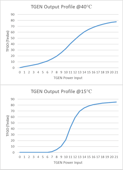 The power input to a toridal generator is represented by the variable TGPI. At low levels of power, field creation is extremely inefficient until a power/output response inflexion is reached, after which efficiency quickly improves before peaking (this inflexion point defines the generator’s nominal output). Beyond nominal, response to any additional power input becomes increasingly less efficient.
Initial modelling suggests that nominal TGPI is approximately 11 units, producing approximately 40 kT (kiloTeslas).
The generator's response profile changes with temperature (see Temperature Efficiency Factor below). At higher temperatures the profile is less responsive and overall output dimishes. At lower temperatures, the profile is more reesponsive around nominal TGPI and overall output increases. However, response becomes more volatile, with generator output dropping to minimum at higher TGPI levels.
Generator Reponse Profile Function
The generator response profile can be represented with the following (cumulative distribution) lorentzian function:
where x is the power input (TGPI), n is nominal TGPI and w is the generator’s Temperature Efficiency Factor (TEF) (representing the function's mathematical 'width') - see below for detail on how the TEF is calculated.
Modifiers
The output of these functions is multiplied by a modifer in order to ensures values consistent with the overall simulation model.
The output of the generator response profile (cumulative function) has a zero modifier (currently 10) subtracted from the value in order to ensure zero output at zero power levels. All output values below zero are normalised to zero. At extreme temperatures this can cause small visual aberrations on a graph of the generator response profile.
Operating Factors
The response profile is affected by the following operating factors:
Temperature Efficiency (TEF)
 While described as ‘room-temperature’ superconductors, this only means that the generator coils do not have to be at super-cold (approaching absolute zero) temperatures in order to exhibit superconducting characteristics.
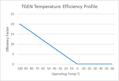
The generator coils do have a maximum operating temperature (approx. 100°C) beyond which they lose their superconducting characteristics. The generator coils also have an increasingly efficient response profile at lower temperatures: peak output remains constant but higher output levels are available more quickly along the power input response curve.
This is not only results in more efficient output below nominal power levels but reduces the spikiness of generator output response at power levels near/around nominal, improving operability.
Initial modelling suggests that optimal efficiency is attained at an operating temperature of approximately 20°C.
Temperature Effciency Factor Function
The efficiency profile of the generator at a given operating temperature is input into the generator response profile function as the Temperature Efficiency Factor (TEF). The TEF can be represented as:
Where x is the current operating temperature (OpTemp - see below), and r is a ratio representing the operating efficiency of the cooling system and m is a system profile modifier.
The higher the TEF, the less efficiently the generator is operating. The generator reaches peak efficiency at an operating temperature of zero degrees celcius, with a TEF of 0.1 (the generator enever reaches perfect efficiency due to slight, unavoidable flaws in the makeup of the superconductor).
Operating Temperature (OpTemp)
The operating temperature is managed by the Tertiary Cooling System (TCS), which offsets radiant heat from the reactor chamber. Each toridal generator has its own TCS unit.
The tertiary coolant system is extremely robust and only requires low power levels to operate. The trade-off is a poor efficiency profile in response to increased power levels.
Operating Temperature Function
The tertiary cooling system’s response profile can be represented as:
Where x is the cooling system's power input, h is the environmental heat load, s is the generator’s efficiency factor and m is a system profile modifier.
TCS Operating Conditions
Operation of the TCS is impacted by conditions not described above, such as the availability of liquid coolant. These conditions may modify the output of the operating temperature function and are described in a separate article (TBA).
Outputs
Applied Toroidal Force (ATF)
Toroidal generator output is passed on to the poloidal generator sim as Applied Toroidal Force (ATF). This a measure of the lorenztian force currently being applied by the field to a constant position, a field plane representing the nominal Reaction Volume (nRV). It is measured in Amperes per square meter (A/m2). It is used by the poloidal generator sIm to calculate the shape and position of the toridal field.
Response Profile
At a certain TGPI level the AFP becomes too close to the origin and begins adversely interacting, diminishing ATF.
Function
The ATF is calculated using the simple function:
where t is TFGO, x is TFGI and p is AFP.
Effective Reaction Volume (ERV)
There are four poloidal generators and each of their output is applied to the ATF of each toroidal generator to determine the AFPF and Containment Field Pitch. These outputs are taken back into the Toroidal SImulation to calculate the Effective Reaction Volume (ERV) for each toroidal generator.
For the purposes of calculating the ERV, the (minimum) AFPF outputs from each poloidal generator are averaged before being applied to the ERV function, as are the CFP outputs.
ERV is measured in cubic meters (m3).
It is calculated as a standard torus volume (base volume) with additional volume added to reflect the variance of containment field lines caused by the containment field pitch.
Base Volume
 Base volume is calculated as
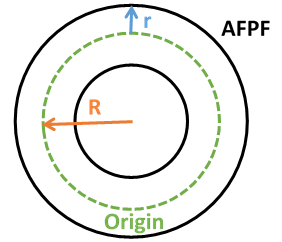
Where R is the major radius, represented by the toroidal origin and r is the minor radius, representing the distance from origin to the AFPF. To calculate the minor radius, the AFPF at the generator (furthest point (22 degrees) from the meridian, where the AFPF value is at its lowest) is used. This is referred to as the minAFPF.
This volume is divided by 16 the number of generators (eight).
Effective Reaction Volume
The eRV is calculated by adding the additional volume created by containment field line distortions to the base volume.
Where bV is the base volume and C is the containment field pitch (CFP).
This is then divided by two, to reflect the fact that each generator contributes half of the reaction volume for each segment (see visualisation notes above). The ERV's of facing generators are later added together in the plasma simulation to form the Segment ERV (segERV).
Segment Effective Reaction Volume
The plasma system operates within reactor segments created by the output of two facing toroidal generator systems. Each toroidal generator effectively contributes half of its ERV (one half on each side of the generator, each a mirror image) to each of two facing segments. As each toroidal generator might have a different power output (and therefore a different ERV), to allow the plasma system to operate on a segment basis the ERV of each toroidal generator is split at the generator (22.5 degrees from the segment meridian) and added to the split output from the facing toroidal generator, to create the Segment Effective Reaction Volume (segERV) which is described in the plasma simulation overview.
Categories:
Attachment:
Concept Site
Immersive sci-fi and how to join the adventure
Crew Site
Information and tools for ISDC crew members


