


Impulse Navigation Module
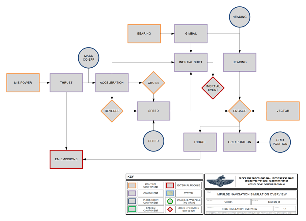 The Impulse Navigation module is a backend API that calcuates vessel movement on a impulse navigation grid based on thrust and bearing variables set by console controls. The module pulls data on the vessel's current location, heading and speed as part of calculations.
The module is used by any active vessel or TSMO.
The module calculates navigation actions for one maneuvering cycle. At the beginning of each cycle, the module is called and the current value of helm controls is used to calculate the navigation actions for that cycle. The length of the maneuvering cycle is dependent on how often the module is called (usually every one second).
Units of Measure
The impulse navigation simulation is grid-based, with a grid being 3000km square.
A grid unit is the lowest unit of measure possible, as the system locates an object by grid co-ordinates made up of integers.
Helm Maneuver
Helm maneuvering involves applying directional thrust to alter the vessel's heading. It is entered into the system by deciding how many degrees to adjust the current direction of travel by (the bearing) and the distance traveled during the maneuver (velocity). The system will triangulate bearing and velocity to calculate how many X and Y grid co-ordinates the vessel has moved during the maneuver (the grid shift). X and Y grid shift is rounded to the nearest integer.
 For example, a maneuver bearing 30° at a velocity of 3 grids/sec gives a grid shift of X3, Y2.
A negative bearing indicates a turn to the vessel's starboard side. A positive bearing indicates a turn to the vessel's port side. As the bearing represents a change in direction of travel it is added to the current heading to give the new heading.
Users select the bearing or vector by which they wish to adjust the vessel's direction. When ready, the user will engage the helm maneuver, which results in the module calculating the resulting changes in heading or vector in the next maneuvering cycle.
The vessel's new position is calculated by adding the grid shift to the vessel's starting position at the beginning of the maneuver.
For example, the vessel has a starting grid position of X100, Y100 with a heading of 90°. A helm maneuver bearing 30° velocity 3 grids/sec is executed. The vessel's new position is X103, Y102 with a heading of 120° (previous heading 90° plus a bearing of 30°).
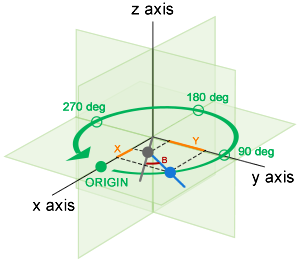
Grid Shift Calculation
The maneuver's X and Y grid shift (in orange on the diagram) form the adjacent (X) and opposite (Y) sides of a right-triangle. The hypotenuse (blue) is calculated using the new heading (angle from adjacent side) and velocity (length).
where X and Y are the grid shift values for those axes, H is the vessel's pre-maneuver heading, B is the maneuver's bearing and V is the maneuver's velocity.
Velocity Calculation (Speed)
The vessel's speed is retrieved in km/sec and is converted to grids per cycle. This value is used as the maneuver's velocity.
Maneuver Stages
Helm maneuvers with higher bearings are broken down into multiple stages to better represent natural vessel movement. A bearing of 90° would not manifest as a sharp right-angle turn - it would be a curve described by the vessel's speed and inertia (or leeway).
 The maneuver's velocity and bearing are divided by the number of maneuvering stages and each stage is calculated cumulatively.
Gimbal Limits
Helm maneuvers are carried out by changing the direction of engine thrust, which causes the ship's heading to change in the opposite direction. This process is referred to as gimballing the engines. The maximum extent to which the direction of thrust can be changed is referred to as the engine's gimbal limit.
The vessel's speed influences the amount of heading change for a given gimbal angle. The faster the vessel's speed, the larger a heading change that can be acehived with the same gimbal angle.
Gimbal limits are caculated differently depending on the engine mode:
Where the helm maneuver is engaged in drive mode, no additional thurst is applied. Only the current thrust is used to achieve the maneuver, so the gimbal limit is calculated based on the maximum radial acceleration that system can handle:
where L is the maximum radial acceleration supported by the system (for Endeavour this is 460), b is the maneuver's bearing and s is the vessel's speed (in C).
Where the helm maneuver is engaged in cruise mode, additional thrust must be applied, so the gimbal limit is based on how much power the engines can handle. The gimbal limit is calculated as:
where M is maximum power input the engines are rated at (for Endeavour this is 12) and P is the actual power applied to the engines to generate thrust for the maneuver.
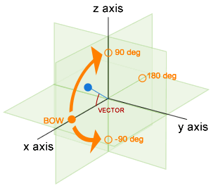
Vector Changes
A vector is a vertical bearing. The system calculates a grid shift on the Z-axis if the maneuver includes a vector.
No vertical heading is currently recorded as helm maneuvering is restricted as much as possible to X and Y axes. The vessel automatically returns itself to a zero vector on completion of the maneuver.
where T is the vector, V is the maneuver velocity and Z is the Z-axis grid shift of the maneuver.
Excess Vector
Vectors above 90° are not possible.
Multiple Maneuvering Cycles
By default, the impulse navigation will apply the helm maneuver settings only within a single maneuvering cycle, after the user engages the maneuver.The settings will not be applied again until the user engages the maneuver again.
For example, the vessel has a heading of 90° and a meaneuver of bearing 10° is engaged. On the next maneuvering cycle, the vessel's heading changes to 100° and remains at that value through the following maneuver cycles until the next time a helm maneuver is engaged.
If the helm's hold mode is selected then the current bearing will be applied for each maneuvering cycle until hold mode is deselected. This allows the vessel to maintain a curved flight path across multiple maneuvering cycles.
Thrust
 The amount of thrust delivered by the impulse engines is controlled from the helm, where the quartermaster applies power to the engines to deliver the required thrust.
When the MIE simulation system is completed, Thrust will be calculated by that system. For initial training and simulation purposes, a thrust calculation function is included in the impulse navigation module.
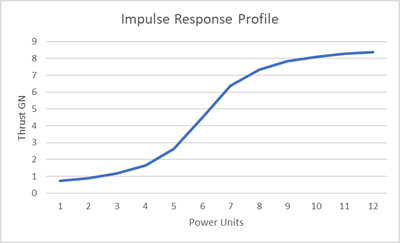
Response Profile
Efficiency of the impulse engines varies over their operating range. The response profile is described by a Lorentzian cumulative distribution function.
where x is the power input, n is nominal power input and p is the engine performance co-efficient.
EM Emissions
Engine thrust produces substantial EM emissions. The impulse navigation module calls the correct EM Output Profile and uses this to calculate the thrust level of the current maneuvering cycle.
EM output is calculated for each band as:
where E is the EM output, x is the thrust being generated by the engines, T is the value of the thrust stage defined in the output profile, and M is the value of the EM stage defined by the output profile.
Minimum EM Output
As a result of operating requirements the engines output some EM whether thrust is being applied or not. This minimum is defined by the min value for each band in the EM Output Profile.
Helm Manuevering and Thrust
Changes in the vessel's direction are achieved by varying the direction of thrust. Where the vessel is not in drive mode (ie no thrust is being applied as with cruise mode - see below), then power is automatically applied to the engines to generate sufficient thrust to acheive the maneuver.This will increase the EM emissions accordingly.
This power applied to the engines to generate thrust for a helm maneuver in cruise mode is calculated as:
where P is the power automatically applied to the engine to generate thrust, B is the maneuver's bearing, S is the vessel's current speed (expressed as C), T is a modifier describing the thrust required to move a given mass and M is the mass-co-efficient of the vessel.
If thrust is already being applied in drive mode, then no additional thrust is required for helm maneuvers and there is no impact on power levels or EM emissions.
Acceleration
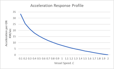 Acceleration is the conversion of thrust into vessel movement, described as the number of grid units added to speed per maneuvering cycle (GU/sec2). Grid units are not displayed on crew-facing consoles – the units will be converted to KM/sec2 or C for crew use.
The operational mode where thrust is adding tovessel speed is referred to as drive mode.
Relativistic Drag
As the vessel travels faster, it encounters relativistic drag which increases the effective mass of the vessel. This reduces the amount of acceleration produced for the same amount of thrust (as there is effectively more vessel to push).
The response profile describing this is based on an inverse log function.
Where x is thrust in GN, f is the vessel’s mass co-efficient (based on the vessel’s mass), C is the vessel’s current speed in units of C, S is a speed modifier and M is a system modifier.
Reverse Thrust and Deceleration
The vessel has a system of plasma diverters and forward-facing impulse thrusters that can decelerate and stop the vessel. Thrust is applied in reverse mode, which produces deceleration (is this value is subtracted from speed rather than added).
Reverse thrust introduces inefficiencies which are reflected as a modifier to the acceleration function.
where x is thrust, A is the acceleration that would have resulted from that thrust (using the above function) and R is the reverse modifier representing the efficiency loss.
All Stop and Reverse Direction
By default, the reverse mode will automatically cut thrust when the vessel's speed reaches zero, being the vessel to all stop.
If the hold mode is enagged while the reverse mode is also engaged then the vessel will apply reverse acceleration. This allows the vessel to be reversed if needed.
Cruise Mode
Helm users may nominate a target cruising speed. Once the vessel has accelerated to that speed, thrust will automatically be cut and the speed maintained by the vessel's inertia. This operating mode is referred to as cruise mode.
Radial Acceleration
Acceleration as calculated above describes linear movement of the vessel. Additional acceleration forces are applied to the ship during helm maneuvers (away from a linear movement path). This is referred to as radial acceleration (or "inertial shift"). Factors such as speed and bearing/vector all contribute to radial acceleration.
where s is the vessel's current speed (in grids/cycle), b is the bearing (or vector) of the helm maneuver, l is the linear acceleration (uncorrected for relatavistic drag, so calculated at a fixed speed value of 0.01C) and m is a modifier (value of 500). This gives the radial acceleration r in m/sec/sec.
Where a helm maneuver includes both a bearing and a vector, the two are calculated indepdently and the acceleration added together.
G-Force
G-force describes the application of acceleration to the interior spaces of the vessel and the crew. G-force is calculated by dividing acceleration by 9.8 (which describes Earth gravity).
Concept Site
Immersive sci-fi and how to join the adventure
Crew Site
Information and tools for ISDC crew members


