


Related

The FTL (Faster Than Light) Drive is a piece of recovered extra-terrestrial technology that emits intensive gravimetric fields capable of manipulating space-time.
The vessel's main propulsion is provided by Magnetoplasma Impulse Engines (MIE's), which utilise terrestrially-developed magnetoplasma technology combined with an alien-derived magneto-impulse acceleration system.
Power Distribution Network (PDN) block schematics provide an overview of the network and to allow for the configuration of network components. Distribution nodes and the power sources and vessel systems connected to them are all represented on the PDN as nodes. Nodes are connected by conduits which provide an overview of available distribution pathways for power.
Nodes
Nodes manage the distribution of power around the PDN. Nodes are represented by rectangular symbols which provide basic information about each node. Tapping a node symbol opens that node's configuration interface..
Depending their type, a node can receive power via its upstream interface and supply power via its downstream interface.
Each interface can accommodate up to three 'taps' which connect to conduits to receive or supply power.
Depending on the requirements of the schematic design, node symbols can be oriented with the upstream interface on the left (as in the examples shown) or reversed so that the upstream interface is on the right.
Node Symbols
Node types are represented by three symbols. The symbols may also have different colours to indicate their function (or their current status).
Distribution Nodes
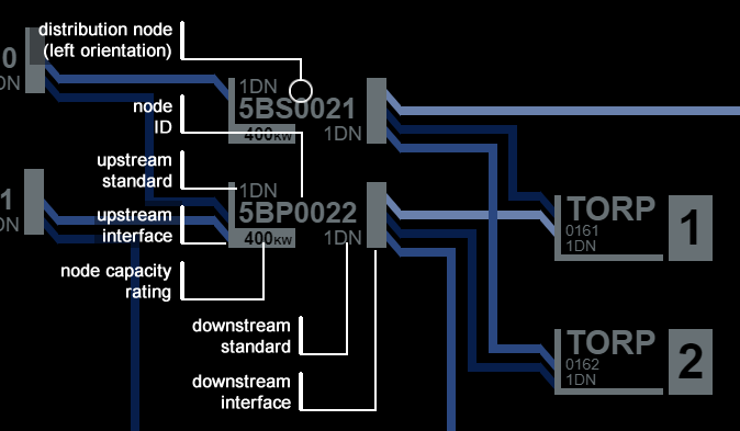
Distribution nodes are the most common type of node. They receive power via their upstream interface and distribute power to other nodes (possibly after converting to a different power standard) via their downstream interface.
The symbol for a distribution node is a rectangle enclosing data regarding the node’s designation and rating. The narrow vertical line to one side of the symbol represents the node’s upstream interface. The wide vertical line to the other side of the symbol represents the node’s downstream interface.
UPS Nodes
UPS nodes are distribution nodes that also contain battery power storage, to cover temporary outages in power for critical systems. UPS node symbols use the same layout but are coloured green.
Node Symbol Data
Node symbols display data about the configuration of that node.
Upstream Interface Standard: This identifies the power standard the node can receive.
Node ID: This is the node's UID.
Rated Capacity: This identifies the node's rated power distribution capacity.
Downstream Interface Standard: This identifies the power standard the node distributes.
System Nodes
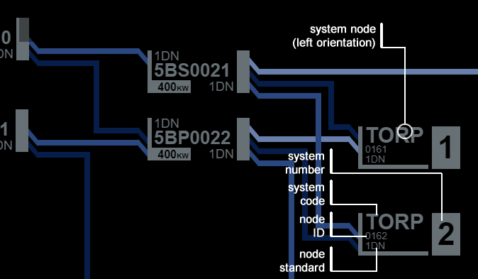
System nodes are the next most common type of node. They are represented by a different symbol to reflect that they only receive power for consumption and so only have an upstream interface. The upstream interface is represented by a narrow vertical line on one side of the symbol.
Node Symbol Data
Node symbols display data about the configuration of that node.
Node Standard: This identifies the power standard the system can receive.
Node ID: This is the node's UID.
System Code: This identifies the system represented by the node. Where there are multiple systems of the same type, each system is given an additional number designation.
Generator Nodes
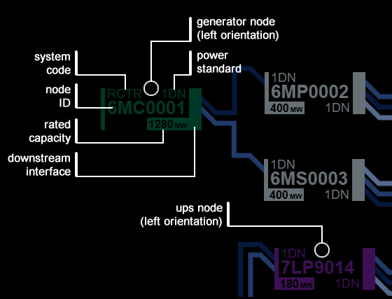
Generator nodes produce power and so only have a downstream interface. As such, the symbol used for a generator is slightly different from a distribution node and the symbol's colour is purple.
The downstream interface is represented by the wider vertical line on one side of the symbol.
Node Symbol Data
Node symbols display data about the configuration of that node.
Power Standard: This identifies the power standard the node delivers.
Node ID: This is the node's UID.
System Code: Generators have system codes to assist with the identification
Rated Capacity: This identifies the node's rated power generation capacity.
Conduits
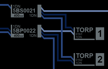
Power is delivered between nodes by conduits. A node connects to a conduit via a conduit tap on either its upstream or downstream interface.
The node supplying power to a conduit is the upstream node. The node receiving power from a conduit is the downstream node.
Conduit Symbols
Conduits are represented by coloured horizontal or vertical lines, with a different colour representing each distinct conduit.
Conduits never connect to other conduits, only to nodes. If a conduit crosses another on a schematic, no connection between the two is implied.
A conduit tap (connecting to a node) is represented by an angled line which ‘flows’ in the direction of power delivery. For example, a conduit tap to a node’s upstream interface will always meet the node symbol at a point vertically lower than it meets the connecting conduit.