


PDN schematics overview
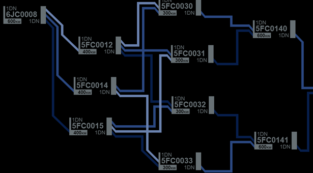
Power Distribution Network (PDN) block schematics provide an overview of the network and to allow for the configuration of network components. Power sources and vessel systems connected to them are all represented on the PDN as nodes. Nodes are connected by conduits which provide an overview of available distribution pathways for power.
PDN schematics on consoles have an edit mode which allows them to be drawn or edited.
Nodes
Distribution nodes are the most common. They receive power from other nodes upstream from them and make power available (usually converted to a new power standard) to nodes downstream from them.
A node receives power via its upstream interface and supplies power via its downstream interface. Depending on the requirements of the schematic design, node symbols can be oriented with the downstream interface on the right or reversed so that the downstream interface is on the left.
") Each interface can accommodate up to three 'taps' which connect to conduits to receive or supply power.
Each interface can accommodate up to three 'taps' which connect to conduits to receive or supply power.
System nodes represent vessel systems and as such only have upstream interfaces - they receive power but do not distribute it.
Node Symbols
Nodes are represented by two types of symbol. The symbol for a distribution node is a rectangle enclosing data regarding the node’s designation and rating. The wider vertical line to one side of the symbol represents the node’s upstream interface.
To facilitate different schematic layouts, the node symbols are reversible. The upstream interface is always represented by the wider vertical line regardless of which side of the symbol it is on.
Tapping a distribution node symbol provides access that node’s monitoring and control interface.
The symbol for a system node displays only system designation information and is distinguished by its extra wide upstream interface.
Node Data
Node symbols display data about the configuration of that node.
Upstream Interface Standard: This identifies the power standard the node can receive.
Node ID: This is the node's ID. The last four numbers are a unique numeric ID for the node. The first three characters identify where in the ship the node is located:
- The first character (a number) number is the deck
- The second character is the section
- The third character identifies where in the section - S for starboard, P for port, C for centre
For system nodes, only the unique four-number ID is displayed.
Rated Capacity: This identifies the node's rated power distribution capacity (distribution nodes only).
Downstream Interface Standard: This identifies the power standard the node distributes (distribution nodes only).
Conduits
Power is delivered between nodes by conduits. A node connects to a conduit from either its upstream or downstream interface via a conduit tap.
The node supplying power to a conduit is the upstream node. The node receiving power from a conduit is the downstream node.
Conduit Symbols
 Conduits are represented by coloured horizontal or vertical lines, with a different colour representing each distinct conduit.
Conduits never connect to other conduits, only to nodes. If a conduit crosses another on a schematic, no connection between the two is implied.
A conduit tap (connecting to a node) is represented by an angled line which ‘flows’ in the direction of power delivery. For example, a conduit tap to a node’s upstream interface will always meet the node symbol at a point vertically lower than it meets the connecting conduit.
Conduit Tap Orientation
Conduit taps may have different orientations in the schematic to support required layouts. Conduit taps may be oriented horizontally where a horizontal schematic flow is required.
Alternatively, conduit taps may be oriented vertically where a vertical schematic flow is required.
Categories:
Concept Site
Immersive sci-fi and how to join the adventure
Crew Site
Information and tools for ISDC crew members


